Exploring ADCS Principles: A Technical Deep Dive into Attitude Determination and Control Systems
Authored by Afan Huang
A technical deep dive into ADCS (Attitude Determination and Control System): sensors, actuators, math, algorithms, modes, and real mission practices.
This article explains the core principles, math, and algorithms behind an Attitude Determination and Control System (ADCS), from sensor fusion and guidance to control allocation and safe modes, so teams can plan, size, and verify ADCS with confidence.
ADCS Architecture and Components
Attitude Determination and Control System (ADCS) is a spacecraft subsystem that delivers two interdependent functional domains:
-
Attitude Determination (sensing and estimation): fuses measurements from magnetometers, coarse/fine sun sensors, star trackers, gyros, Earth-horizon sensors (and sometimes GNSS aiding) to estimate attitude and body rates (the spacecraft’s rotation rates about its own axes) in real time.
-
Attitude Control (guidance and actuation): converts mission pointing/slew requirements into torque commands and applies them through reaction wheels, magnetorquers, control-moment gyros (CMG/VSCMG), or thrusters; includes mode logic (e.g., Sun pointing, detumble) and momentum management.
Modern smallsat programs often use integrated ADCS units (sensors, actuators, and flight software packaged together) to simplify integration and reduce commissioning time.
〈Related Reading:Attitude Determination and Control Systems (ADCS): An In-Depth Analysis from Sensing to Control〉
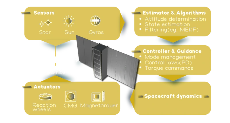
ADCS Components
ADCS Operational Sequence
The ADCS executes a recurring sequence that estimates the spacecraft attitude and rates, generates a reference attitude, computes control torques, allocates them to actuators, and then measures the result, closing the loop in discrete time. This sequence is standard across flight implementations, independent of vendor naming.
〈Related Reading:Keys toward precise attitude control〉
State Propagation (kinematics & dynamics)
Between measurements, flight software propagates the attitude and body rates using rigid-body models:
-
Attitude Kinematics (quaternion):

-
Rotational Dynamics:

Symbols: "q" unit quaternion; "w" body angular-rate vector; "J" inertia matrix; "Tcmd" commanded control torque; " Tdist" environmental/disturbance torque. These equations are the standard basis for on-board estimation and control.
Measurement Update (estimation)
At each sensor update, the estimator combines star-tracker attitude solutions, the Sun vector, the magnetic-field vector, and gyro rates to correct drift in the propagated state. Single-epoch methods such as TRIAD and the QUEST algorithm computer attitude directly from the sensor measurements available at one instant. Most flight software uses a Multiplicative Extended Kalman Filter for continuous estimation of attitude and angular rate while keeping the quaternion normalized.
Guidance and Mode Management
Guidance selects a pointing objective and enforces motion limits. Mode management decides which objective is active and when to transition, so the spacecraft stays safe, power-positive, and within pointing/jitter budgets.
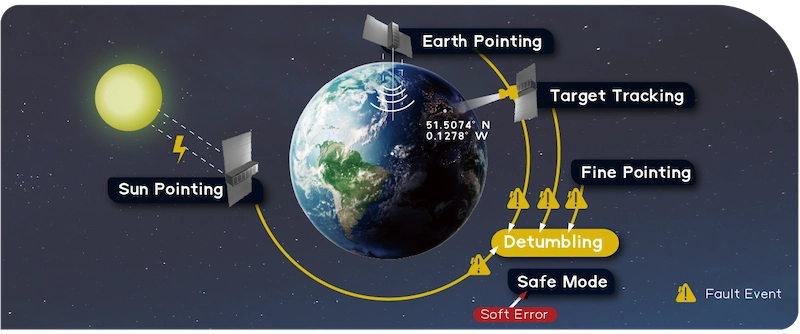
Generic ADCS modes
Guidance selects a pointing objective and enforces motion limits. Mode management decides which objective is active and when to transition, so the spacecraft stays safe, power-positive, and within pointing/jitter budgets.
-
Detumble
Reduce the initial high body rates to near zero using low-complexity controllers, typically magnetorquers. This is the first step after separation and a recovery entry point after faults.
-
Sun Pointing
Aim a defined body axis toward the Sun to secure power and thermal margin during commissioning or low-activity periods.
-
Safe Mode
A contingency state that prioritizes power/thermal safety and rate limits while higher-level functions are suspended. Exact behavior depends on the mission design; include only if your system implements it.
-
Earth Pointing Mode
Align the body frame with the orbital velocity and the earth pointing vector.
-
Fine Point Mode
User-defined satellite attitude control within Earth-Centered Inertial frames.
-
Target Tracking Mode
Control the satellite to track a ground object.
Guidance and Mode Management
Control Law (torque computation)
The controller maps attitude error and body rate to a commanded torque that meets pointing and slew limits. In practice, missions use simple proportional–derivative control for most operations and switch to more advanced controllers only when needed. The commanded torque is then passed to the actuator allocation step.
Actuator Allocation
Commanded torque is mapped to the available actuators subject to saturations and constraints:
-
Reaction wheels: allocate via a geometry matrix from body torque to wheel torques and schedule momentum desaturation via magnetorquers or thrusters when stored momentum grows.
-
Magnetorquers (MTQs): produce torque " T = m X B " from magnetic dipole and Earth field " B " ; widely used for detumble and unloading.
-
CMGs/VSCMGs: high torque-to-mass actuation with steering laws that avoid/transition singularities (beyond the scope here).
Actuation and Closed-loop Response
Actuators apply the commanded torques; the spacecraft responds per the dynamics above; sensors measure the resulting attitude and rates; the estimator updates while completing the loop and starting the next cycle. This loop is implemented in discrete time with task rates matched to sensor/actuator timing.
Mathematical Foundation of ADCS
An Attitude Determination and Control System (ADCS) depends on well-established mathematical models and algorithms. These models and algorithms provide a unified framework to represent orientation, estimate attitude from noisy sensor data, and compute control commands that respect spacecraft dynamics and actuator limits.
Attitude Representations
-
Direction Cosine Matrix (DCM): A 3×3 orthogonal matrix that transforms vectors between inertial and body frames.
-
Quaternions: A four-parameter unit vector representation. Quaternions avoid singularities of Euler angles and are numerically efficient, which is why they are used in almost all modern ADCS flight software.
-
Euler Angles: Three sequential rotations (roll, pitch, yaw). Useful for intuition but limited by singularities (gimbal lock).
Attitude Estimation
-
Vector-based attitude determination (Wahba’s problem)
Given body-frame measurements and their inertial references (with weights), compute the attitude that best aligns them by minimizing a weighted least-squares cost. A widely used onboard solver for this problem is the QUEST algorithm, which computes the attitude quaternion efficiently by solving a small 4x4 matrix equation.
-
TRIAD (two-vector solution)
This method uses two vector pairs. Each pair consists of a body-frame measurement and its inertial-frame reference. The algorithm builds orthonormal bases and then computes the attitude directly. It is simple and fast, but it is less robust when measurements are noisy or when more than two vectors are available.
-
Continuous estimation (MEKF / EKF)
The filter integrates gyro rates and then corrects the state when star-tracker, Sun sensor, or magnetometer measurements arrive. It maintains a unit quaternion by updating only a small error rotation. The result is a numerically stable estimate of attitude and body rates suitable for flight software.
Control Algorithms
-
Proportional–Derivative (PD) Control:

where "e" is a small-angle error vector, and "w" is the measured body rate. Simple, robust, and widely used.
-
Linear Quadratic Regulator (LQR): The Linear Quadratic Regulator (LQR) minimizes a quadratic cost on attitude error, angular rate, and control effort, yielding state-feedback gains that balance maneuvering performance with actuator limits.
-
B-dot Detumbling:

where "mcmd" is the commanded magnetic dipole and "B" is the time derivative of the measured field.
A magnetic detumbling algorithm. It commands magnetorquer dipoles proportional to the negative time derivative of the measured magnetic field. Robust and efficient for rate damping.
-
Singularity-Robust Steering (for CMGs): It ensures commanded torques remain achievable as CMG gimbals approach singularities, using pseudo-inverse or optimization methods.
Supporting Math Tools
-
Attitude Error Metrics: Compute differences between estimated and commanded orientations using quaternion multiplication or small-angle approximations.
-
Torque Allocation: Solve for actuator commands subject to constraints (e.g., distributing torque among multiple wheels).
-
Inertia Matrix Transformations: Use principal moments of inertia and coordinate transforms to related torques, angular rates, and angular accelerations.
-
Vector Geometry: Project sun or magnetic field vectors into body axes for comparison with onboard models.
Why These Algorithms Matter
Without these mathematical foundations, ADCS cannot meet pointing accuracy, agility, or safety requirements. Whether a CubeSat stabilizing after deployment or a science mission requiring milliarcsecond pointing, the robustness of estimation and control algorithms defines mission success.
Applications and Mission Scenarios for ADCS
The Attitude Determination and Control System (ADCS) performs mission-dependent functions. This section summarizes common scenarios, their guidance objectives, and principal performance considerations.
〈Related Reading:ADCS Testbed Innovations: Accelerate Your Satellite Development〉

Application and Mission Scenarios for ADCS
Launch, Early Orbit, and Commissioning
After separation, rates are high and attitude knowledge is coarse. ADCS stabilizes the body, acquires a power-positive orientation, establishes reference frames, and transitions into routine pointing without exceeding thermal or power margins.
Earth Observation
Imaging passes demand nadir alignment, step-stare or scan patterns, and scheduled repoints between targets. ADCS manages bounded-rate slews, meets pointing and stability budgets through each exposure, and returns to the next attitude with minimal settle time.
Astronomy and Long-Exposure Science
Long integrations require inertial holds with low disturbance. ADCS maintains small attitude errors over defined intervals, executes precise dithers when commanded, and keeps micro-disturbances within limits set by the optics and structure.
Communications
Reliable communication depends on maintaining continuous pointing of the antenna or optical terminal toward the ground station. ADCS maintains tracking throughout each communication pass, executes planned re-pointing at the start and end of contact periods, and limits drift and reacquisition time so link quality remains consistent.
Agile Retargeting
Time-critical observations call for rapid, bounded-acceleration maneuvers. ADCS executes the commanded profile end-to-end, respects rate and torque envelopes, and finishes with controlled overshoot so the payload can start immediately.
Platform and Proximity Operations
When work is referenced to the orbit such as platform tasks, servicing, or visiting-vehicle operations, the spacecraft must hold attitudes defined in the Local-Vertical/Local-Horizontal frame. ADCS maintains that geometry against environmental torques and orbital motion.
Deep-Space Cruise
Far from Earth, operations emphasize Sun-positive power, thermal safety, and intermittent target acquisition. ADCS sustains long-duration stability, supports autonomous transitions between cruise and observation attitudes, and functions without reliance on geomagnetic torque.
Constellations and High Duty Cycles
Repetitive profiles across many vehicles demand consistency. ADCS executes the same attitude scripts pass after pass, preserves timing at mode boundaries, and keeps pointing performance uniform across the fleet.
Fault Response and Safe States in Flight
When anomalies occur, ADCS must keep the spacecraft power-positive and thermally safe while preserving a path back to operations. A common approach is a Sun pointing safe state that uses simple sensors and control logic to acquire the Sun within a defined cone, limit body rates, and maintain margins until ground authorizes the exit.
A practical sequence is: detect the fault, stabilize body rates, acquire the Sun, hold within specified angle and rate limits, and provide deterministic transitions back to nominal pointing once health is confirmed. Effective implementations define unambiguous entry and exit conditions, bound time-to-acquire, enforce rate and torque limits, minimize dependencies, and stream the telemetry needed for recovery.
ADCS: Recent Practices and Reader Questions
What are the recent developments in ADCS technology?
Core estimation and control methods are well established (MEKF, QUEST, PD/LQR). Ongoing work focuses on integrated software stacks, agile steering for CMGs, and robust commissioning and safe-state logic that tolerate partial sensor/actuator availability.
Do teams update ADCS software on orbit?
Yes. Teams often upload configuration updates and occasionally software patches once the spacecraft is operational. Typical updates include calibration constants, momentum-management schedules, and refinements to fault-handling logic. Because any change carries risk, these updates are applied under strict ground verification and approval before uplink.
How long does an ADCS last?
ADCS service life is not a fixed number. It is bounded by mission duration and by wear and aging in actuators and sensors. Reaction wheel bearing and lubricant life, CMG gimbal and rotor wear, duty cycle, and the momentum-management plan are the primary mechanical drivers. Radiation exposure and thermal cycling age gyros, star trackers, and avionics. Design margins, derating, redundancy, and safe operating modes extend useful life. Magnetorquers generally outlast wheels because they have no moving parts. On-orbit recalibration and software updates can slow performance drift but cannot reverse mechanical wear. Most programs assign an ADCS design life equal to or slightly longer than the mission and verify it through life testing and environmental qualification.
How is detumbling performance evaluated?
Detumbling performance is usually defined by measurable criteria: the maximum body rates the system can reduce after separation, the time required to bring those rates below a specified threshold, the power consumed during the sequence, and the conditions for handover to Sun pointing or nominal operations. Magnetic control remains the standard method in small-satellite commissioning when Earth’s magnetic field is available.
Tensor Tech ADCS – Delivering Precision Navigation in Space
With quantifiable pointing accuracy, agile slews, and compact packaging, Tensor Tech’s ADCS portfolio supports missions from CubeSats to 1000-kg class spacecraft. Our CMG solutions, powered by spherical-motor architecture, further extend agility and torque authority.
〈Related Reading:What is a TestBed? Practical Application in Satellite ADCS〉
ADCS for 1–30 kg
A compact ADCS for CubeSats, offering fine pointing and agile maneuvers while fitting within tuna-can form factors.
-
Pointing knowledge: 3 arcsec with star tracker (0.3 deg standard)
-
Control accuracy: 0.1 – 0.4 deg (model dependent)
-
Slew rate: > 5 deg/s
-
Max torque: up to 0.12 Nm
-
Momentum capacity: 13 – 41.6 mN·m·s
-
Mass: ~0.44 – 1.58 kg
-
Packaging: tuna-can + 0.25U or discrete, RS-485 / UART
A magnetorquer-only variant is available for coarse control and commissioning, sized at just 0.2U and ~1 W consumption.
SmallSat ADCS for 30–1000 kg
Scalable systems built for higher payload classes, with CMG options for agility.
-
30 – 200 kg (with CMG): < 10 arcsec pointing, > 3 deg/s slews, ~6.4 N·m·s momentum
-
200 – 500 kg: < 10 arcsec pointing, > 3 deg/s slews, ~12.8 N·m·s momentum
-
500 – 1000 kg: < 10 arcsec pointing, > 3 deg/s slews, ~32 N·m·s momentum(An entry configuration without CMG for 30 – 200 kg provides ~5 deg pointing at < 3.2 kg and < 14 W.)
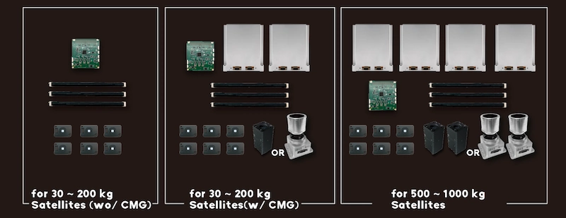
TensorTech ADCS series
CMG with Spherical Motor Innovation
Tensor Tech’s CMG is powered by a single spherical motor that drives both rotor spin and gimbal actuation. This eliminates slip rings, reduces moving parts, and achieves a high torque-to-power ratio in a compact form. The result is agile slews and large momentum storage without sacrificing reliability.
〈Related Reading:What Is a Control Moment Gyroscope (CMG)? A Powerful Solution for Satellite Attitude Control〉
〈Related Reading:Revolutionizing Satellite Attitude Control: Spherical Motor-driven Control Moment Gyroscope〉
Why Tensor Tech
-
Miniaturization with performance
-
Scalability
-
Agility
-
Proven in orbit
Conclusion
An ADCS keeps a spacecraft oriented, stable, and recoverable under real disturbances. Its core uses well-defined mathematical models and flight-proven algorithms, including quaternion and DCM orientation models, Wahba’s problem solved onboard with QUEST, continuous estimation with the MEKF, proportional–derivative control for holds and routine slews, Linear Quadratic Regulation for tighter transients, and B-dot control for rate acquisition during commissioning.
Effective implementation starts with measurable requirements such as pointing accuracy and stability, allowed slew and settle times, jitter windows, volume and power limits, autonomy for faults, and expected service life, and then flows into a pointing and control-performance budget. Verification then closes the loop with hardware-in-the-loop tests, mode-transition checks, momentum-management exercises, and on-orbit calibration updates.
Tensor Tech provides integrated nanosatellite ADCS and scalable SmallSat systems, including CMG solutions driven by a spherical-motor technology for higher agility. Public specifications and in-orbit data on our product pages offer concrete values for early trade studies and help map mission requirements to an implementable ADCS design.
To learn more about our ADCS or discuss how it can support your satellite program, please Contact Us
〈Related Reading:An introduction to fine sun sensors〉