Reaction Wheels and Control Moment Gyroscopes in Satellite ADCS: A Technical Comparison
Authored by J. Wu, A. Huang
Reaction wheels are widely used actuator architecture in satellite attitude determination and control systems (ADCS), generating control torque through angular acceleration of a spinning rotor along a fixed axis. Control moment gyroscopes (CMGs) represent an alternative architecture, redirecting stored angular momentum through gimbal motion. As spacecraft platforms diversify in scale and agility requirements, actuator architecture selection increasingly depends on mission-specific inertia and slew characteristics.
This discussion compares reaction wheels and CMG architectures from an engineering perspective, focusing on torque generation mechanisms, power–torque relationships, system volume implications, and mission-level trade-offs relevant to satellite ADCS.
Reaction Wheels: Operational Characteristics and Mission Applications
Reaction wheels generate control torque by accelerating or decelerating a flywheel spinning about a fixed axis. When the wheel speed changes, conservation of angular momentum produces an equal and opposite torque on the spacecraft body. This angular momentum exchange mechanism enables continuous three-axis control without propellant consumption.
According to NASA’s 2025 Small Spacecraft Technology State of the Art Report, miniature reaction wheels span multiple performance levels across small spacecraft platforms. While higher-capacity units are documented, reaction wheels commonly deployed in CubeSat and low-mass small satellite missions typically provide peak torque below approximately 0.05 Nm, with momentum storage on the order of 10⁻³ to 10⁻¹ Nms. Peak power consumption for these configurations generally falls within single-digit to low-tens of watts, aligning with the inertia and agility characteristics of low-mass spacecraft.
Reaction wheel systems generally employ one wheel per control axis, with three units providing three-axis control and additional wheels providing redundancy. When accumulated momentum approaches saturation limits due to environmental disturbance torques, magnetorquers or thrusters unload stored momentum.
Their independent-axis architecture is commonly implemented in spacecraft operating under moderate slew requirements and limited onboard power availability, particularly in distributed CubeSat and small constellations where mass and power resources are constrained.
High-Agility Mission Profiles and Torque Scaling
Actuator selection becomes increasingly influenced by the relationship between spacecraft inertia and commanded slew rates. Required instantaneous torque scales with spacecraft inertia and commanded angular acceleration, coupling mechanical demand directly to available system power.
In low-inertia platforms, moderate angular accelerations require torque levels within the operating range of typical reaction wheels. As spacecraft size and payload mass increase, the spacecraft moment of inertia rises accordingly. Control torque follows the relation τ = I × α; therefore, maintaining comparable retargeting performance requires proportionally higher torque levels as inertia increases. The simplified dimensional scaling shown below illustrates this relationship under constant-density scaling assumptions.
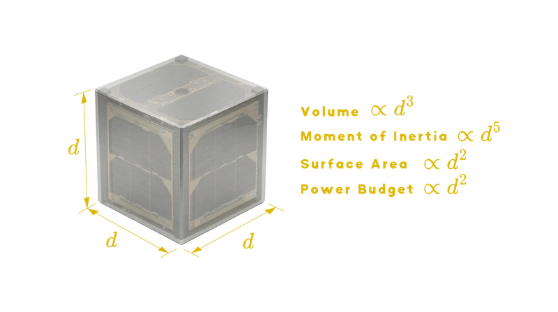
a simplified dimensional scaling of spacecraft physical properties
High-agility Earth observation missions, rapid retargeting scenarios, and platforms requiring frequent large-angle maneuvers impose higher instantaneous torque demand. Under such conditions, the power–torque behavior directly constrains system-level design.
Control Moment Gyroscopes Using Spherical Motors
Control moment gyroscopes generate torque through gyroscopic precession rather than direct rotor acceleration. A spinning rotor maintains approximately constant angular velocity, and control torque is produced by rotating the rotor’s angular momentum vector via a gimbal mechanism. Because torque generation is not directly proportional to rotor acceleration, the power–torque relationship differs from that of reaction wheels. A more detailed explanation of this mechanism can be found in our overview of control moment gyroscope technology.
〈Related Reading:What Is a Control Moment Gyroscope (CMG)? A Powerful Solution for Satellite Attitude Control〉
Comparative analysis by Votel and Sinclair describes CMGs as exhibiting significantly different torque-to-power characteristics relative to reaction wheel systems under certain mission conditions. CMGs redirect stored momentum vectors without proportional increases in rotor acceleration.
CMGs using spherical motors eliminate traditional slip rings by integrating multi-axis actuation within a unified geometry. A detailed architectural treatment of slip ring elimination mechanisms is discussed separately. In single-unit comparisons, spherical motor CMGs occupy approximately 1 r³ of bounding volume, compared to 0.5 r³ for a typical reaction wheel unit. However, at the system level, a four-unit pyramid configuration of reaction wheels may require 6.6 r³ due to orthogonal packaging constraints, whereas a four-unit spherical motor CMG cluster can occupy approximately 4 r³ because the external geometry remains constant during gimbal motion.
〈Related Reading:Eliminating Slip Rings in CMGs Using Spherical Motors〉
Actuator evaluation therefore includes system-level integration geometry in addition to single-unit metrics.
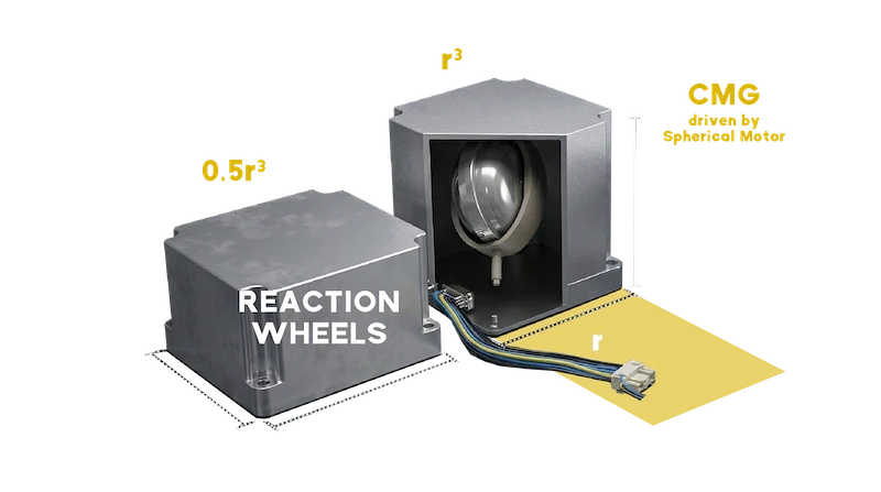
Volume comparison among Tensor Tech’s Control Moment Gyroscope by spherical motor, and Reaction Wheel based on a single unit.
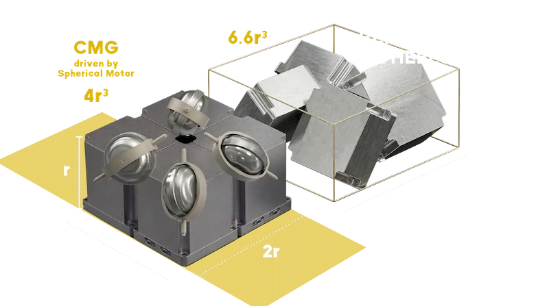
System volume of a four-actuator pyramid cluster.(reaction wheels vs. CMGs based on the spherical motor)
Mission-Specific Performance Comparison
Case A: Planet Dove Constellation
The Planet Labs Dove constellation provides an example of reaction wheels deployed at scale in small satellite platforms. The eoPortal mission documentation describes Flock-3k 3U imaging CubeSats with a mass of approximately 5 kg operating in distributed constellation architectures. More than 200 such satellites have been deployed to provide daily global Earth imaging coverage at 3–5 m resolution.
Within this inertia–slew context, reaction wheels operate within the torque and power demands imposed by the platform mass and agility profile. Constellation-based operational strategies reduce the need for extreme single-satellite retargeting agility, as coverage objectives are achieved through distributed tasking rather than high instantaneous torque maneuvers.

Will Marshall, CEO of Planet, holding one of his company’s Dove satellites
Source : https://www.eoportal.org/satellite-missions/planet?utm_source=chatgpt.com#overview
Case B: WorldView-3
WorldView-3 represents a different mission profile. WorldView-3 operates in a 617 km sun-synchronous orbit and supports high-resolution commercial Earth observation. Reported retargeting times of approximately 4–5 seconds reflect a mission profile requiring high instantaneous maneuverability.
Higher structural mass and payload scale increase spacecraft inertia, raising torque demand for rapid retargeting. Ball Aerospace CMGs were selected for this mission class to support sustained high-rate maneuvering aligned with mission priorities.
For missions prioritizing high instantaneous agility, actuator architectures that redirect stored angular momentum without proportional rotor acceleration are evaluated within system power and inertia constraints.
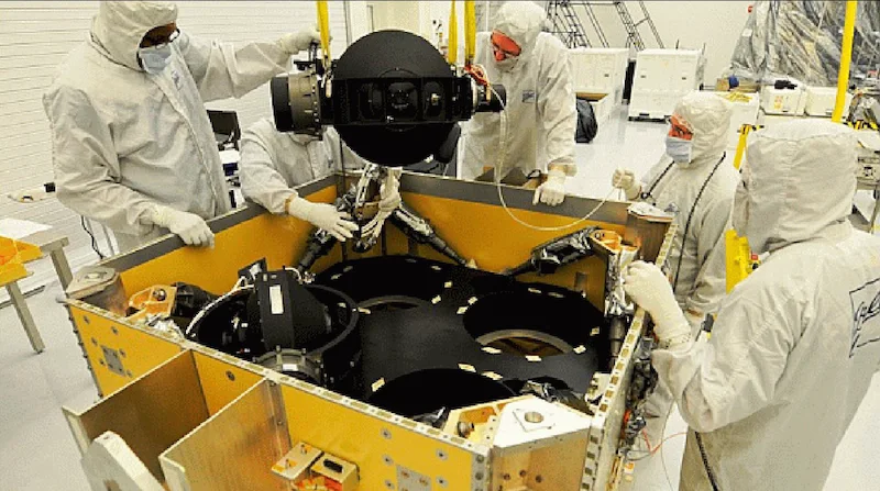
Ball Aerospace engineers install an advanced Control Moment Gyroscope into WorldView-3
Source : https://www.eoportal.org/satellite-missions/worldview-3#spacecraft
Maneuver Power Scaling Analysis
The difference between these mission classes becomes more visible when actuator power is evaluated during maneuver execution. The electrical power consumption of momentum-exchange actuators can be approximated as the sum of mechanical output power and motor losses:
PTotal = PMechanical + PIron + PCopper
where PIron and PCopper represent magnetic core and winding losses in the motor system. During spacecraft slews, the dominant term is typically the mechanical maneuver power required to generate control torque:
PMechanical = PFriction + PManuever [3]

The first term is the mechanical power required to change the angular velocity of the rotors relative to the spacecraft body:
-
For a Reaction Wheel (RW), this maneuver power includes the energy required to accelerate the rotor in order to absorb spacecraft angular momentum. This term becomes larger.
-
For a Control Moment Gyro (CMG), the rotor speed remains essentially constant, and torque is generated by gimbaling. Therefore, WR/S changes very little, making this first term effectively negligible compared to the RW case.
The additional maneuver power consumed by reaction wheels relative to CMGs is therefore governed by three parameters:
-
Spacecraft inertia: larger platforms store more angular momentum, requiring reaction wheels to accelerate their rotors more aggressively during a maneuver
-
Required torque: higher torque demand directly increases the rate of rotor speed change, amplifying power consumption
-
Commanded slew angle: larger slew angles require greater total momentum exchange, raising the peak power demand
Two maneuver regimes determine how this power scales:
-
Bang-bang profile (small slew angles): the spacecraft accelerates then immediately decelerates; peak maneuver power grows with the square root of torque, inertia, and slew angle combined
-
Trapezoidal profile (large slew angles): once the target slew rate is reached, the spacecraft coasts at constant angular velocity; peak power plateaus and only maneuver duration increases.
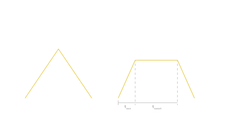
Bang-bang profile & Trapezoidal profile
To illustrate this scaling behavior, three representative spacecraft classes were evaluated spanning nearly three orders of magnitude in spacecraft mass:
| Spacecraft Class | CubeSat-scale platform | Medium Earth observation spacecraft | Large high-resolution imaging spacecraft |
|---|---|---|---|
| Mass (kg) | 5 | 200 | 2800 |
| Total Torque (Nm) | 0.003 | 0.375 | 87.1 |
| Slew Rate (deg/s) | 10 | 5 | 3.5 |
CubeSat-scale platform case
For the CubeSat-scale case, the additional reaction wheel maneuver power remains within only a few watts. The low spacecraft mass fundamentally limits the angular momentum exchange required during any maneuver, keeping reaction wheels well within their operational power envelope for this mission class.
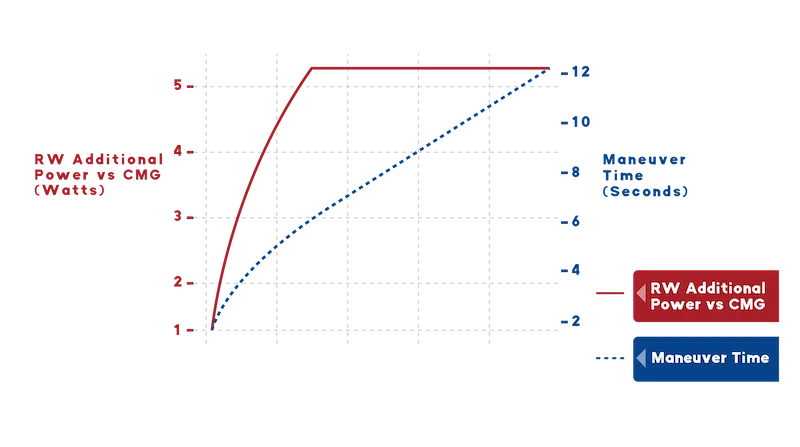
Case 1 : Planet Flock - 5 kg (10 deg/s limit)
Medium Earth Observation spacecraft case
For the medium-class Earth observation case, the required maneuver power rises to the order of tens of watts. As spacecraft mass increases by nearly two orders of magnitude relative to the CubeSat case, reaction wheels must absorb proportionally larger momentum exchanges through rotor acceleration. At this scale, the power difference between RW and CMG architectures begins to affect system-level power budget allocation, particularly for missions requiring frequent retargeting.
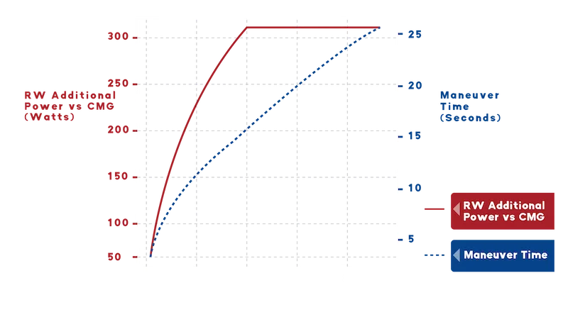
Case 2 : Dummy Satellite - 200 kg (5 deg/s limit)
Large high-resolution imaging satellite case
For the large high-resolution imaging spacecraft case, the additional reaction wheel maneuver power reaches the order of hundreds of watts during rapid retargeting maneuvers. At this mass scale, the momentum exchange required to execute a fast slew becomes substantial, and reaction wheels must accelerate their rotors accordingly. This power demand occurs precisely when the spacecraft's power budget is already heavily loaded by imaging payloads and downlink systems, making actuator power efficiency a critical system-level design consideration.
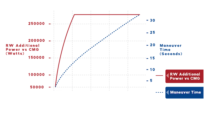
Case 3 : WorldView-3 - 2800 kg (3.5 deg/s limit)
Actuator Selection Under Varying Inertia and Slew Conditions
Actuator selection in satellite ADCS is fundamentally constrained by the inertia–slew relationship that defines required torque. Spacecraft inertia and commanded angular acceleration jointly determine instantaneous torque demand and its interaction with available power and duty cycle limits.
In spacecraft characterized by lower structural mass and moderate slew requirements, required torque remains within ranges typically supported by reaction wheels operating within standard power envelopes.
As platform inertia increases or mission profiles demand sustained high-rate retargeting, torque demand scales proportionally. Under such conditions, actuator architectures capable of redirecting stored angular momentum without proportional increases in rotor acceleration are evaluated within the broader system power envelope. For mission designers, the key decision variable is not which actuator architecture to select, but whether the mission's inertia-slew profile places power demand within or beyond the reaction wheel's operational envelope, a threshold that shifts significantly with spacecraft scale.
References
-
NASA, Small Spacecraft Technology State of the Art Report, 2025. https://ntrs.nasa.gov/api/citations/20250000142/downloads/SOA%202025_Final.pdf
-
Votel & Sinclair, Comparison of Control Moment Gyros and Reaction Wheels, SSC12-X-1. https://digitalcommons.usu.edu/cgi/viewcontent.cgi?article=1080&context=smallsat
-
Tensor Tech, Control Moment Gyroscopes – Pros and Cons, 2025. https://2025.smallsateurope.com/sessions-three/control-moment-gyroscopes-pros-and-cons/
-
eoPortal, Planet Dove Constellation. Accessed 2026. https://www.eoportal.org/satellite-missions/planet?utm_source=chatgpt.com
-
eoPortal, WorldView-3 Mission Overview. Accessed 2026. https://www.eoportal.org/satellite-missions/worldview-3
-
Stephen J. Chapman Electric Machinery Fundamentals, McGraw-Hill, 5th edition. https://elcom-team.com/Subjects/%D8%A2%D9%84%D8%A7%D8%AA%20%D9%83%D9%87%D8%B1%D8%A8%D8%A7%D8%A6%D9%8A%D8%A9%201/%D8%A7%D9%84%D9%83%D8%AA%D8%A8%20%D9%88%20%D8%A7%D9%84%D8%AD%D9%84%D9%88%D9%84/machine-book-(5th-ed)-compressed.pdf