Eliminating Slip Rings in CMGs Using Spherical Motors
Authored by Afan Huang
Control Moment Gyroscopes (CMGs) have become essential actuators for spacecraft requiring high torque output and precise attitude control. Unlike reaction wheels, CMGs generate torque through gyroscopic precession, achieving significantly higher torque-to-power ratios for rapid satellite maneuvers.
Traditional single-gimbal CMG architectures employ two motors: a high-speed rotor motor and a gimbal motor that redirects the spinning rotor's angular momentum. Since the rotor operates on a rotating gimbal platform, continuous electrical power transfer requires slip rings. These electromechanical assemblies represent proven technology with decades of successful spaceflight heritage.
Operational experience from missions ranging from the International Space Station to agile earth observation satellites has informed spacecraft design considerations. For mission profiles where certain operational factors are critical, alternative CMG architectures using contactless actuation offer additional options. This article examines this operational experience and explores how spherical motor technology provides an alternative approach.
Control Moment Gyroscopes and Slip Ring Requirements
CMG Operating Principle
Control Moment Gyroscopes generate attitude control torque by exploiting the gyroscopic effect. A high-speed flywheel spinning at constant velocity stores angular momentum. When a gimbal motor tilts the flywheel's spin axis, the resulting change in angular momentum direction produces a torque perpendicular to both the spin axis and the gimbal rotation axis. This gyroscopic torque amplification enables CMGs to deliver substantially higher output torque than the gimbal motor input, with torque magnitudes proportional to both the flywheel's angular momentum and the gimbal rotation rate.
Gimbal Motor Architectures and Power Transfer
CMG designs employ different gimbal configurations. Single-gimbal CMGs use one gimbal axis to tilt the flywheel's spin axis, while double-gimbal CMGs provide two orthogonal gimbal axes for additional control authority and singularity avoidance. Both architectures require a rotor motor mounted on the rotating gimbal platform to maintain the flywheel at constant high speed, typically ranging from 3,000 to 10,000 rpm depending on the design. The gimbal motor (or motors in double-gimbal designs) controls the orientation of the flywheel's spin axis to produce the commanded output torque. Since the rotor motor rotates with the gimbal structure through unlimited angular range, continuous electrical power transfer across this rotating interface is required.
Slip Rings as the Standard Solution
This rotating electrical interface requirement is conventionally addressed through slip ring assemblies. These electromechanical devices transfer electrical signals and power across the rotating interface using sliding contacts between stationary brushes and rotating conductor rings. Slip ring technology has been refined over decades of aerospace applications, with manufacturers developing specialized materials, contact geometries, and lubrication systems optimized for the space environment. The technology provides a proven, reliable solution that has enabled CMG-based attitude control systems on numerous spacecraft, from large space stations to agile earth observation satellites.
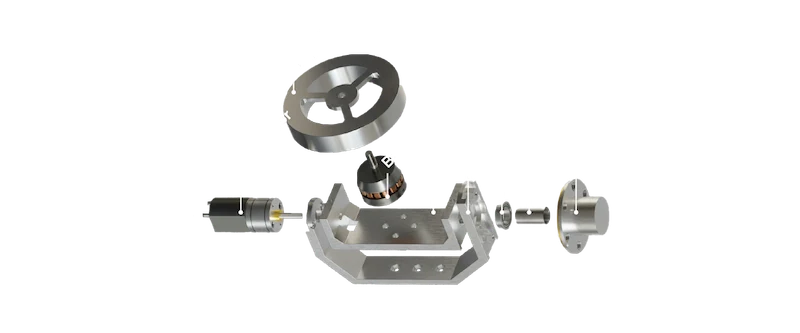
Traditional single-gimbal CMG architecture. The slip ring transfers power and control signals to the rotor motor mounted on the rotating gimbal platform.
Source : https://www.researchgate.net/figure/Exploded-view-of-a-single-CMG-The-brushless-DC-motor-drives-the-fywheel-and-the-DC_fig2_365208956
Mission Experience with Slip Ring CMGs
Traditional CMG architectures rely on slip ring assemblies to transfer electrical power and control signals to the rotor motor mounted on the rotating gimbal platform. While slip ring technology has enabled numerous successful missions, operational experience has revealed specific design considerations that inform spacecraft architecture decisions.
Reliability and Lifetime Considerations: ISS CMG Experience
The International Space Station employs four Double Gimbal Control Moment Gyroscopes, each providing 4,760 Nms of angular momentum and 258 Nm of output torque, designed for 10-year operational lifetimes. The CMG system's operational history illustrates the reliability considerations associated with slip ring-based designs.
Following installation in 2000, the first unit experienced an unexpected failure after 1.3 years of operation in June 2002. Failure investigation revealed bearing wear from mechanical stress, exacerbated by friction in the slip ring assembly during high gimbal rate operations. A third unit developed anomalous behavior after approximately six years, with unbalance sensors reaching shutdown criteria in October 2006. Both failures were attributed in part to mechanical wear in components subjected to continuous sliding contact.
In response, NASA implemented operational restrictions to extend CMG lifetime, reducing gimbal angular velocity limits from 3.1°/s to 0.8°/s and constraining acceleration to 0.04°/s². These modifications reduced mechanical stress on slip ring contacts while maintaining satisfactory attitude control performance. The ISS experience demonstrates that slip ring wear mechanisms can necessitate conservative operational strategies and robust redundancy planning (N+2 configuration) to ensure mission success over multi-decade timeframes.
〈Related Reading:Revolutionizing Satellite Attitude Control: Spherical Motor-driven Control Moment Gyroscope〉
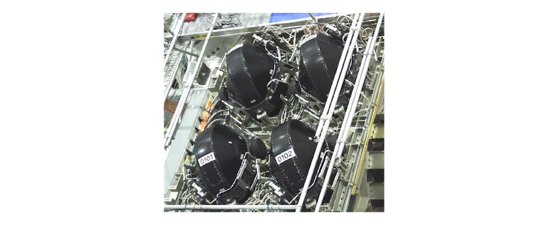
ISS Control Moment Gyroscopes
Source : https://www.researchgate.net/figure/SS-Control-Moment-Gyroscopes_fig3_238108187
Duty Cycle Limitations: Pléiades High-Agility Operations
The Pléiades constellation (launched 2011-2012) represents a demanding operational profile for slip ring-based CMGs. The mission uses CMG 15-45S units developed by Astrium (now Airbus Defence and Space) with 15 Nms angular momentum and 45 Nm output torque to achieve slew rates exceeding 3°/s for responsive earth observation. The frequent gimbal movements significantly exceed traditional satellite pointing requirements, placing substantial demands on slip ring lifetime.
Recognizing slip ring wear as a mission-critical design constraint, CNES (the French space agency) conducted extensive qualification testing before flight. Vacuum chamber tests simulating operational conditions were required to validate that the slip ring assemblies could complete 5 million displacements (representing 2.5 million satellite maneuvers) without performance degradation, with friction remaining below 13 mNm. This testing directly addressed concerns about slip ring durability under high-duty-cycle operations.
The four satellites (Pléiades-1A, 1B, SPOT-6, SPOT-7) using this CMG technology have accumulated over 35 years of combined on-orbit operations. However, achieving this lifetime required careful mission planning to manage cumulative gimbal motion and distribute wear across multiple CMG units. These operational constraints illustrate how slip ring lifetime limitations can impose duty cycle restrictions on agile satellite missions.
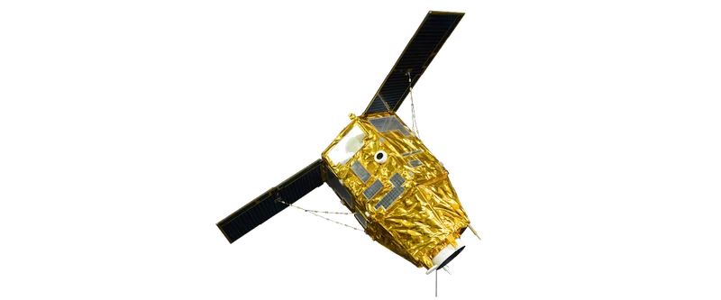
Pléiades satellite
Source : https://en.wikipedia.org/wiki/Pl%C3%A9iades_%28satellite%29
Architectural Constraints: Channel Limitations and Design Trade-offs
Beyond wear considerations, slip ring assemblies impose architectural constraints on CMG design. The number of electrical channels through a slip ring is physically limited by the available circumference and the need to maintain electrical isolation between conductors. This constraint has traditionally restricted CMG architectures to constant-speed rotor operation, as implementing variable-speed control would require additional power and signal channels beyond what compact slip ring assemblies can reliably accommodate.
The combined operational experience from ISS, Pléiades, and other missions has established industry practices including:
-
N+1 or N+2 redundancy configurations to accommodate slip ring wear-related failures
-
Conservative gimbal rate limits during non-critical mission phases to preserve lifetime
-
Wear-distribution algorithms to balance gimbal motion across multiple CMG units
-
Constant-speed rotor operation to minimize slip ring channel requirements
These design considerations and operational restrictions inform system-level trade studies for missions with extended lifetimes, high agility requirements, or constraints on redundancy mass. While slip ring technology continues to enable successful missions, mission profiles with particular combinations of these factors may benefit from alternative architectural approaches that address these specific design considerations.
How Spherical Motor CMGs Work
Traditional CMG architectures employ two separate motors: a rotor motor to maintain flywheel spin and a gimbal motor (or motors) to control orientation. This dual-motor configuration requires the rotor motor to be mounted on the rotating gimbal structure, necessitating continuous electrical power transfer across the rotating interface through slip ring assemblies.
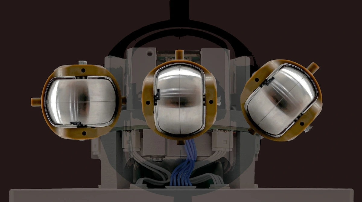
Spherical motor-based CMG designs integrate both functions into a single electromagnetic structure. The spherical motor simultaneously drives the rotor's high-speed rotation and controls its three-dimensional orientation. The rotor contains permanent magnets that interact with multi-axis control coils embedded in the surrounding stator structure. These stator coils are driven with multi-phase current waveforms to generate rotating magnetic fields. This self-contained, all-magnetic architecture eliminates slip rings entirely, as the rotor is driven purely through magnetic fields from the stationary stator. Electrical power is supplied only to the fixed stator coils, with no electrical connection required to the rotating rotor assembly.
〈Related Reading:What Is a Control Moment Gyroscope (CMG)? A Powerful Solution for Satellite Attitude Control〉
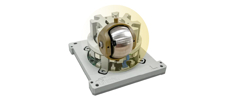
TensorCMG driven by spherical motor
TensorCMG Product Line
The TensorCMG series employs this spherical motor architecture across a range of satellite platforms. The technology was validated in 2022 aboard a 3U optical remote sensing satellite launched on a SpaceX rocket. The design has been validated through over 30 million gimbal cycle tests across the product line. Slip ring-based CMG designs typically qualify for 2-3 million gimbal maneuvers, representing more than 10× improvement while eliminating contact wear as a limiting factor.
The product line serves satellites ranging from CubeSats to platforms up to 1000 kg. Detailed specifications are available for satellites up to 30 kg and satellites over 30 kg. The spherical form factor remains consistent regardless of rotor orientation, unlike traditional gimbaled designs where skewing the gimbal axis to achieve control authority increases the system's occupied volume.
When This Approach Makes Sense
The spherical motor CMG architecture addresses the key design considerations associated with slip ring assemblies through its integrated electromagnetic drive system.
Reliability Considerations
The elimination of slip ring wear mechanisms removes the mechanical degradation observed in traditional systems. The all-magnetic drive system eliminates friction and debris generation from sliding electrical contacts. For missions requiring extended operational lifetimes, this architecture removes one wear-related failure mode that can necessitate conservative operational strategies or increased redundancy in slip ring-based designs.
Duty Cycle Flexibility
Without slip ring lifetime constraints, the spherical motor architecture permits unrestricted gimbal motion throughout the mission. High-agility missions requiring frequent or continuous gimbal movements are not subject to duty cycle limitations imposed by cumulative wear on sliding contacts. The contactless magnetic drive enables unlimited gimbal rotation range without the wire management constraints that can affect slip ring assemblies.
Variable-Speed Capability
Traditional CMG designs maintain constant-speed rotor operation due to slip ring channel limitations. Implementing variable-speed control would require additional power and signal channels beyond what compact slip ring assemblies can accommodate. The spherical motor architecture eliminates this constraint. The integrated electromagnetic structure enables variable-speed rotor operation without requiring additional electrical pathways through a rotating interface. The ability to adjust rotor speed dynamically provides operational flexibility not practical in traditional constant-speed architectures constrained by slip ring channel count.
| Aspect | Traditional CMG with Slip Ring | Spherical Motor CMG |
|---|---|---|
| Wear-related failures | Slip ring contact wear | No contact wear |
| Rotor speed | Constant speed (channel limited) | Variable speed capable |
| Operational lifetime | 2-3M gimbal cycles typical | 30M+ cycles validated |
Conclusion
This approach represents an additional option in the CMG design space rather than a replacement for traditional architectures. The selection between slip ring-based and spherical motor-based designs depends on specific mission requirements, operational profiles, and system-level trade-offs. Traditional CMG designs continue to provide proven, reliable performance across a wide range of applications, while spherical motor architectures offer particular advantages for missions where these specific design considerations are driving requirements. For mission-specific consultation,visit.

References
-
Gurrisi, C., et al. (2010). "Space Station Control Moment Gyroscope Lessons Learned." 40th Aerospace Mechanisms Symposium. NASA/TM-2010-21932. https://ntrs.nasa.gov/citations/20100021932 https://ntrs.nasa.gov/api/citations/20100021932/downloads/20100021932.pdf
-
Defendini, A., et al. (2003). "Control Moment GYRO CMG 15-45 S: a compact CMG product for agile satellites in the one ton class." European Space Mechanisms and Tribology Symposium. https://www.esmats.eu/esmatspapers/pastpapers/pdfs/2003/defendini.pdf https://www.researchgate.net/publication/241585778_Control_Moment_GYRO_CMG_15-45_S_a_compact_CMG_product_for_agile_satellites_in_the_one_ton_class https://www.researchgate.net/publication/253734541_A_Compact_CMG_Product_for_Agile_Satellites
-
Wikipedia contributors. "Pléiades (satellite)." Wikipedia, The Free Encyclopedia. https://en.wikipedia.org/wiki/Pl%C3%A9iades_(satellite)
-
Airbus Defence and Space (2015). "NEWTON products enable agile satellite missions." https://www.ukspace.org/newton-products-enable-agile- satellite-missions/
-
SpaceNews (2015). "Airbus Defence and Space NEWTON Products Enable Agile Satellite Missions." https://spacenews.com/airbus-defence-and-space- newton-products-enable-agile-satellite-missions/
-
Selvaggi, J.A.; Salon, S.; Chari, M.V.K.; Kwon, O.; Vaschetto, S. "A Permanent Magnet Synchronous Spherical Motor for High-Mobility Servo- Actuation," Machines, vol. 10, no. 8, p. 612, 2022. https://doi.org/10.3390/machines10080612 https://www.mdpi.com/2075-1702/10/8/612
-
Chabot, J.A. "A Spherical Magnetic Dipole Actuator for Spacecraft Attitude Control," M.S. Thesis, University of Colorado, 2018. https://hanspeterschaub.info/Papers/grads/JoshuaChabot.pdf
-
Control Moment Gyroscopes: Pros and Cons," SmallSat Europe Conference, 2025. https://2025.smallsateurope.com/sessions-three/control-moment-gyroscopes- pros-and-cons/
-
Blue Canyon Technologies. "Blue Canyon Technologies Delivers Control Moment Gyroscopes to Commercial Customers." News Release, December 30, 2024. https://www.bluecanyontech.com/news/blue-canyon-technologies-delivers-control-moment-gyroscopes-to-commercial-customer/