An introduction to fine sun sensors
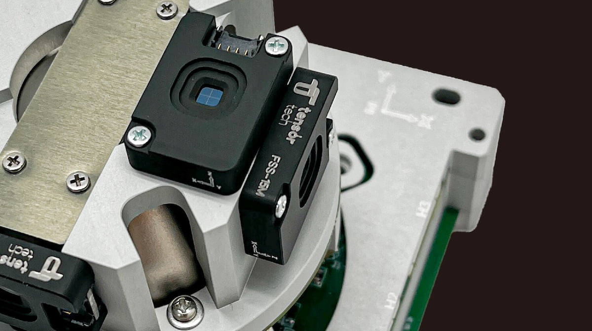
Authored by Luke Hou
Fine sun sensors (FSS) are essential tools in modern spacecraft for accurately determining the Sun’s position. In this article, we explore how fine sun sensors work, their types, differences from coarse sun sensors, and practical applications in satellite attitude determination and control systems (ADCS).
What is Sun Sensor?
Sun sensors are critical components in satellite attitude determination and control systems (ADCS). These devices precisely measure the incident angle of solar radiation, providing essential data for satellite orientation and positioning in space.
Classification and Types
Sun sensors are broadly categorized into two main classes based on their precision and functionality:
1. Coarse Sun Sensors (CSS)
Coarse sun sensors provide basic directional information of sunlight and are typically used for initial attitude acquisition or backup orientation sensing. They feature a simple design, are low-cost, and consume minimal power, though their accuracy is limited compared to fine sun sensors.
2. Fine Sun Sensors (FSS)
a. Analog Output Fine Sun Sensors
Analog fine sun sensors output voltage levels corresponding to the angle of sunlight incidence. These require external analog-to-digital converters (ADC) for processing, making them ideal for systems with tight power budgets but with higher noise susceptibility.
b. Digital Output Fine Sun Sensors
Digital fine sun sensors integrate internal signal processing, outputting digital data directly through communication interfaces like RS485 or UART. They offer improved noise immunity, onboard calibration capabilities, and are well-suited for high-precision satellite missions.
Output Behavior of Coarse Sun Sensors
Coarse sun sensors produce variable output signals depending on the Sun’s position within their field of view (FOV). Typically built with a single photodiode or photoresistor, these sensors are power-efficient but sacrifice accuracy due to their simple structure.
Coordinate Frame and Angle Output of Fine Sun Sensors
A fine sun sensor outputs two angular components — alpha and beta — defining the sun vector in its reference frame, typically described in a right-handed coordinate system. In contrast, coarse sun sensors only provide the alpha angle. This dual-axis output makes FSS far more informative for precise spacecraft orientation.

Definition of the fine sun sensor reference frame
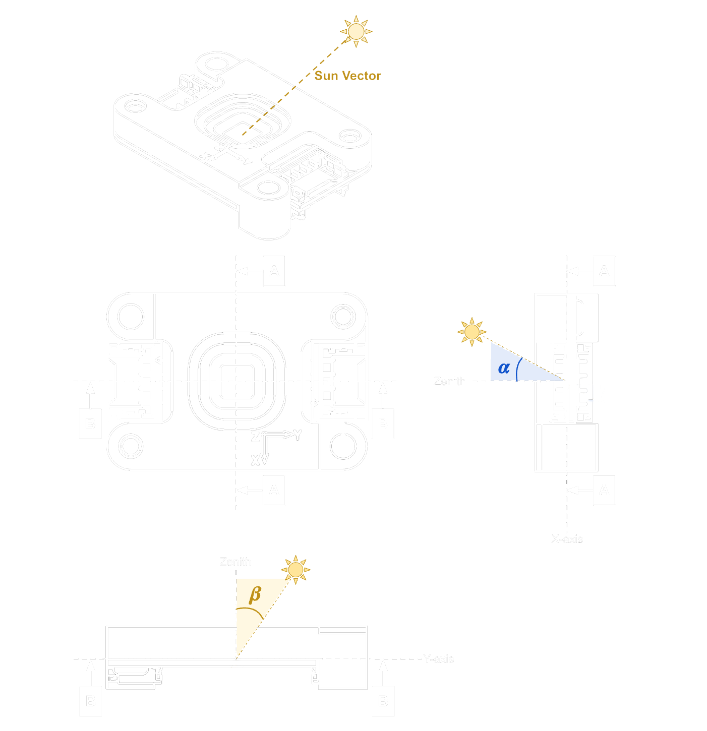
Definition of the fine sun sensor reference frame in spherical coordinate system
Analog vs. Digital Fine Sun Sensors – Key Differences
Analog fine sun sensors use voltage signals to represent angular data and require external ADCs, while digital models embed the ADC and microcontroller within the sensor.
Digital FSS connect directly to the satellite’s attitude control computer using interfaces like RS485 or UART. They may consume more peak power but provide enhanced accuracy through onboard noise reduction and error correction mechanisms.
Three common types of sun sensors
| Classification | Features | ||
|---|---|---|---|
| sun sensor | Coarse sun sensor | Only provide the relative strength of the sun | |
| Fine sun sensor | digital fine sun sensor | ● output digital signal ● less external circuit ● less noise ● more power consumption *comparing with the analog-type fine sun sensors |
|
| analog fine sun sensor | ● output analog signal ● less peak & average power consumption *comparing with the digital-type fine sun sensors |
||
Power Consumption Considerations
Although digital fine sun sensors often show higher peak current draw during sampling, their average power consumption is generally comparable to analog sensors. This makes them viable even for missions with limited power budgets, especially when precision is prioritized.

Example current consumption profile of digital-type fine sun sensor and analog-type fine sun sensor
How does a Fine Sun Sensor function?
A rectangular aperture allows sunlight to project a light spot onto a photodiode array inside the sensor. The location of this light spot is used to calculate the direction of the sun.
A quad-cell photodiode array, consisting of segments Q1 to Q4, detects the position of the sunlight. The current from each cell indicates how much light hits that segment. By analyzing these values, the sun’s incidence angles can be calculated. The digital version includes a built-in MCU to convert the analog signal to digital before transmitting it to the satellite system.
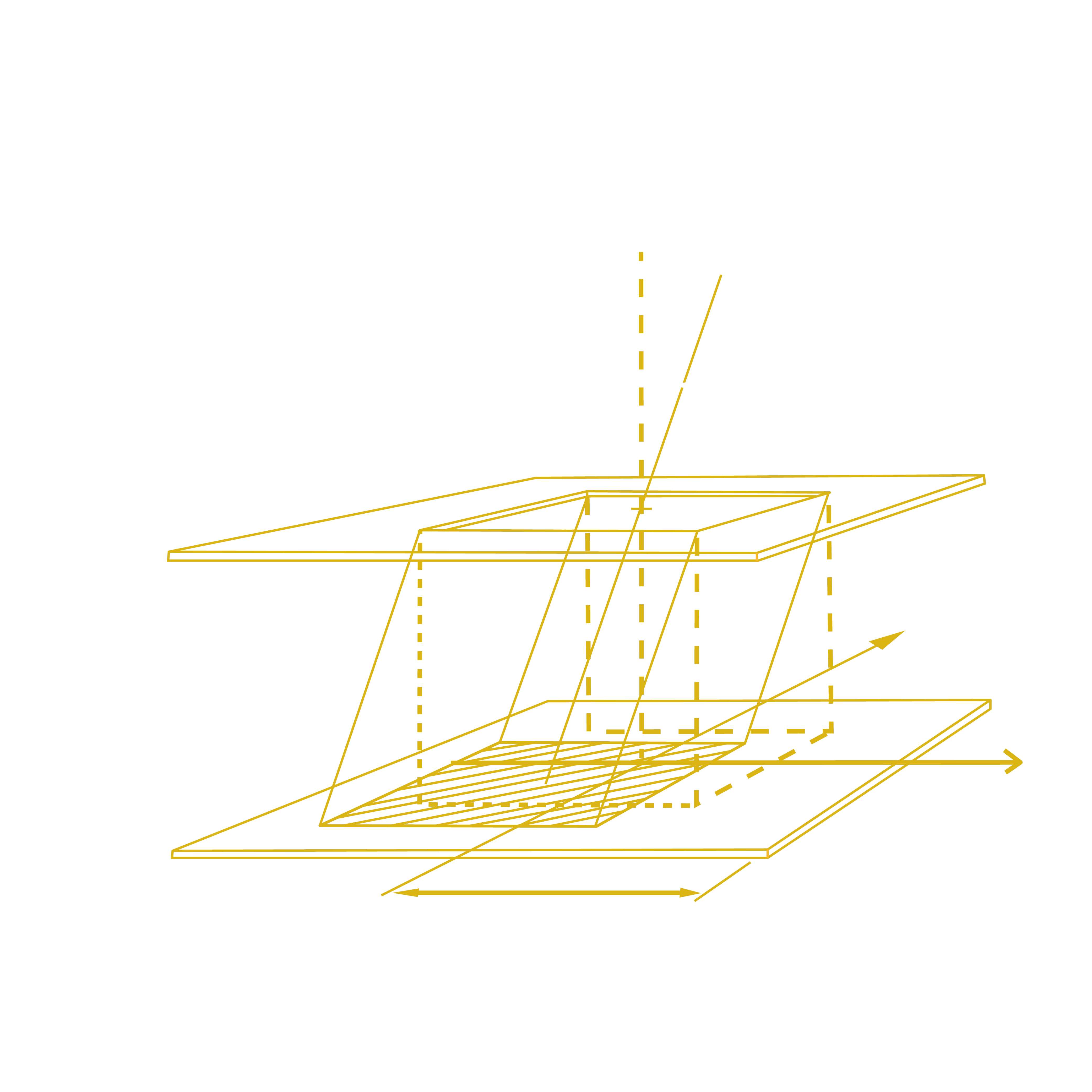
Reference:E. Boslooper, N. Heiden, D. Naron, R. Schmits, J. Velde, and J. Wakeren. (2012). BepiColombo fine sun sensor. International Conference on Space Optics.
Tensor Tech’s Digital Fine Sun Sensor: TensorFSS-15M
Tensor Tech's fine sun sensor, TensorFSS-15M, is a digital-type model. Compared to analog versions, it offers higher precision, reduced signal noise, and direct compatibility with the satellite's onboard computer via RS485. Its integrated design streamlines system integration and improves attitude control reliability.
〈Related Product Recommendations:Fine Sun Sensor〉
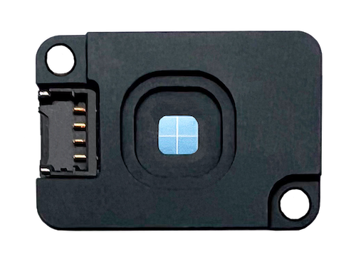
TensorFSS-15M
Other applications
Sun sensors are widely used in spacecraft attitude determination systems for measuring the sun vector in spacecraft coordinates. They are also deployed in weather platforms, solar tracking systems, and unmanned vehicles for enhanced orientation and navigation.
Common Questions and Answers
Q1: How does the error of the fine sun sensor induce?
A1: Two primary types of errors exist: system errors and random errors.
System error sources include:
-
Variability among photodiode segments
-
Component tolerance issues (resistors/capacitors)
-
Mechanical misalignment during installation
-
Optical refraction or poor surface modeling
Random error sources include:
-
Electrical noise in photodiode output
-
Sampling errors from ADCS
Misalignment is often the dominant error source. Tensor Tech recommends using its integrated ADCS solutions, where sensors are factory-installed and calibrated, reducing total system error to within 0.1°.
In practice, the albedo effect — light reflected from Earth — can introduce additional error that’s difficult to model precisely.
Q2: How do we calibrate the fine sun sensor?
A2: Calibration is conducted in a controlled darkroom using a dual-axis manual platform and an AM0-grade solar simulator. The true pointing is derived from the mechanical platform, and the sensor’s output is used to build a correction table by comparing the two datasets.
Q3: Where can I install the fine sun sensor on my CubeSat?
A3: Common installation configurations include:
-
Two-sensor layout:One sensor near the deployed solar panel, another on the satellite's top or bottom.
-
Six-sensor layout:One sensor on each satellite face, ensuring full coverage.
-
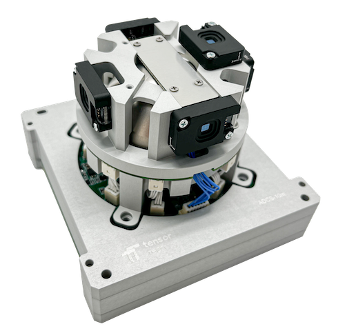
Five-sensor layout:One face excluded due to structural constraints. Tensor Tech’s ADCS uses this configuration, occupying the “tuna can” area on a 3U CubeSat.
Conclusion
Fine sun sensors play a vital role in satellite attitude control, offering high precision and reliability. Whether analog or digital, these sensors are indispensable for accurate solar tracking and spacecraft orientation. Tensor Tech’s digital fine sun sensors provide advanced performance and easy integration for modern CubeSat and small satellite missions.For more information or to discuss your satellite mission requirements, please don’t hesitate to contact us.
〈Related Reading:What Is a Control Moment Gyroscope (CMG)? A Powerful Solution for Satellite Attitude Control〉

