
Fine Sun Sensor with Integrated Magnetometer for SmallSat Attitude Determination
Authored by A. Huang
Attitude determination for small satellites in low Earth orbit typically requires at least two independent vector measurements. A fine sun sensor (FSS) provides a two-axis sun incidence measurement. A three-axis magnetometer provides a magnetic field vector measurement. When combined with an onboard magnetic field model, these two instruments allow full three-axis attitude determination without additional hardware.

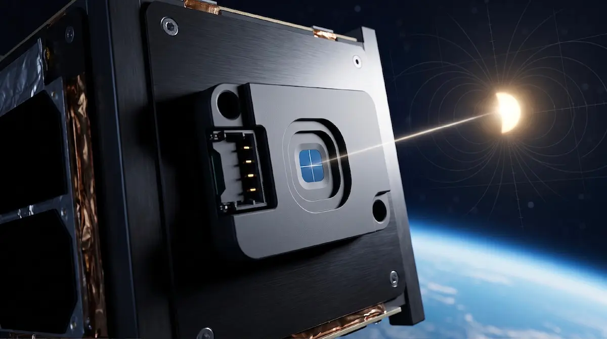
Figure 1. TensorFSS-15M
This article describes the measurement architecture, interface design, and configuration options of TensorFSS-15M for engineers evaluating attitude determination sensor suites for nanosat and small satellite missions.
Sun Vector Measurement
TensorFSS-15M measures solar incidence angles using a photodiode quadrant detector. The output is expressed as two angles, ALPHA and BETA, representing the sun vector in the sensor reference frame.
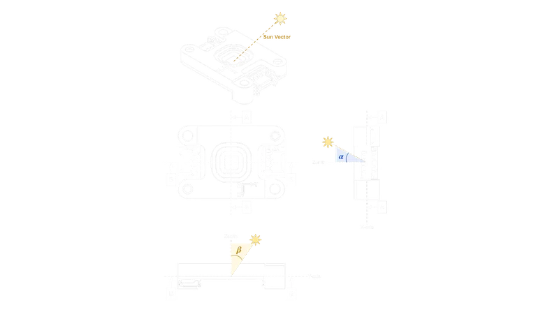
Figure 2. Definition of the fine sun sensor reference frame in coordinate system
Sun vector accuracy is lower than 0.2° across the full 120° field of view. Factory calibration is applied to the photodiode array before shipment, correcting for light-spot alignment error and unit-to-unit variation. Calibration data is stored internally and applied automatically during measurement processing.
The sun vector output data rate is configurable at 4, 8, or 16 Hz. The unit also outputs the total photocurrent measured across the photodiode array. This value remains valid even when the sun is outside the field of view, providing a light-level indication that functions as a built-in coarse sun presence detector.
Magnetometer
TensorFSS-15M includes a tri-axis magnetometer. In continuous mode, the magnetometer samples at a configurable rate, set independently from the sun vector output rate.
The unit outputs calibrated magnetic field values. The calibration model applied in firmware is:
h0=A-1(hF-b)
h0: the calibrated magnetic field vector
A: the soft-iron correction matrix,
b: the hard-iron offset vector,
hF: the raw field reading
The hard-iron offset vector (b) is determined during factory calibration. The soft-iron correction matrix (A⁻¹) is initialized to the identity matrix by default, as soft-iron calibration is not performed at the factory. Both parameters are writable registers. After the unit is integrated into the satellite structure, users can update both parameters to reflect the actual installed magnetic environment, then save them to non-volatile memory for automatic restoration on power-up.
Magnetometer noise is in the range of 7 to 40 nT. The geomagnetic field magnitude in LEO ranges from approximately 25,000 to 65,000 nT. At this signal-to-noise ratio, the dominant error source for attitude determination accuracy is the calibration residual from residual magnetic interference in the satellite structure, not sensor noise.
Distributed Magnetometer Coverage in Multi-Unit Configurations
Most satellite configurations that use fine sun sensors require coverage across more than one face, which means deploying multiple TensorFSS-15M units. Each unit includes a tri-axis magnetometer and outputs both measurements in the same sensor coordinate frame, so the sun vector and magnetic field data from each unit are internally co-registered without additional alignment calibration.
In a multi-unit deployment, the magnetometers are distributed across structurally distinct locations on the satellite. Soft- and hard-iron sources, including motors, wire harnesses, and electronics, introduce magnetic distortion that varies by location. A magnetometer on one face of the satellite may read a significantly cleaner field than one mounted near a high-current path. The ADCS software can compare the magnetometer readings across units and weight the measurement from the location experiencing the least interference, improving the reliability of the magnetic field measurement used in attitude determination. This spatial distribution requires no additional magnetometer hardware beyond the FSS units the mission already carries.
Interface
TensorFSS-15M communicates over RS-485 using 8N1 framing at 115200 baud. The interface is half-duplex. The unit operates as a slave device and responds to register read and write commands from the ADCS host processor.
The unit exposes sun vector data as two angular outputs in the sensor reference frame, and magnetic field data as a three-axis calibrated vector. Both are read over the same physical interface. Sun vector and magnetometer each have independent mode and rate settings. Either function can operate in Continuous or One-shot mode without constraining the other. The unit reports real-time operational status for both the FSS and magnetometer, including initialization results, per-sample success flags, and error codes. ADCS software can query this at startup and during operation to detect hardware faults or measurement failures.
Magnetorquer Interference and Measurement Scheduling
Satellites that use
The standard design response is a duty-cycle approach in the ADCS control loop. Magnetorquers fire for a defined portion of each control cycle, then power off while the magnetometer takes a sample. Published CubeSat implementations allocate around 10% of the cycle period as a magnetically quiet measurement window, with the remaining 90% available for actuation.
TensorFSS-15M's One-shot measurement mode is suited to this architecture. The ADCS processor triggers a magnetometer sample explicitly, at a point in the control cycle when magnetorquers are confirmed off. This gives the software direct control over measurement timing rather than relying on continuous background sampling that may capture data during an active torquer period.
Configuring the Magnetometer at Integration
The magnetometer operating mode is set in firmware at integration time. On units with the magnetometer installed, the function can be deactivated with a single register write if the mission does not require magnetic field data.
Both attitude determination measurements are covered under the same datasheet, integration procedure, and vendor interface. For programs where the magnetometer will not be used, the configuration requires one register write. The physical unit remains the same part number across both cases.
For programs where both measurements are needed, no additional hardware interface is required. The ADCS processor reads the sun vector and magnetic field data over the same RS-485 connection. When the magnetometer function is used, mount the unit at least 10 cm from magnetic interference sources such as motors and high-current wire harnesses.
Flight Heritage
TensorFSS-15M has been in orbit since 2022, across multiple missions. In-orbit data from these missions has been used to validate the calibration model and confirm performance within specification under operational conditions.
The combination of flight heritage and a production-stable register interface reduces integration risk for new programs. Engineers working from an earlier revision of the interface documentation can verify register compatibility against the current user manual revision before committing to board layout.
Further Information
Full specifications, user manual, and interface documentation for TensorFSS-15M are available on the product page. For integration questions or mission-specific configuration support, contact the Tensor Tech engineering team directly.
For integration questions or mission-specific configuration support,

References
-
"Magnetic Fault-Tolerant Attitude Control with Dynamic Sensing for Remote Sensing CubeSats," Remote Sensing, MDPI, 2023. https://www.nasa.gov/content/what-are-smallsats-and-cubesats https://www.mdpi.com/2072-4292/15/19/4858
-
"Implementation and Hardware-In-The-Loop Simulation of a Magnetic Detumbling and Pointing Control Based on Three-Axis Magnetometer Data," Aerospace, MDPI, 2019. https://www.google.com/url?q=https://www.mdpi.com/2226-4310/6/12/133&sa=D&source=docs&ust=1787917253190811&usg=AOvVaw2RJSASI_znWZGz3hjKBTyE/